HOBBY CIRCUITS
Relays and logic gates
Though relays and logic gates are different components, they work
in a comparable way. In this article you can see how I converted a relay based
schematic into a logic gates diagram.
The relay logic circuit is supposed to operate a roll shutter motor and features two run buttons, two limit
switches and a safety switch. When a button is pressed, even for a bit, the motor starts
running; it will be stopped by the limit switch, or by pressing any button, so it works
like a car window.
The buttons feature a double function due to the relays K1 and K2, that are both off at
the start condition. When a button is pressed, the relay K1 turns on. When it is released,
the relays are both on. By pressing a button again, the relay K1 backs off, while the other
one keeps on. By releasing the button, the relays are both off. This circuit schematic
has been tested with a PLC ladder logic simulator.
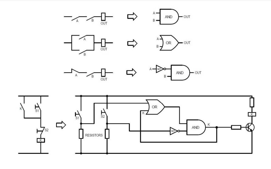
Since they work in a similar way, I associated logic gates and relays connections.
Series connections correspond to AND gates, while parallel connections correspond to OR gates;
normally closed contacts can be compared to NOT gates.
Please note that the image below is just an example on how relay based circuits relate
to logic gates; it doesn't matter with the circuit I'm talking about.
