HOBBY CIRCUITS
How elevators work
The elevator control system consists of all components supposed to manage the operation of the equipment, such as car speed and direction, door closing, acoustic and light signals. It includes the controller (relay or microprocessor based), buttons, proximity sensors, limit and safety switches etc. Early elevators had a manual control system. They required an operator, which drove the car by holding two buttons (up and down). Later, an automatic leveling system was designed by a famous elevator company: once the operator released the control button, the elevator reduced speed and stopped at the nearest floor.
Automatic elevators
The first full automatic elevator control system was installed after the first global war
and worked by relay logic; this technology is still used on old equipment.
The movement of the car is controlled through a direction selector.
This device consists of an exchange (SPDT) switch, whose central pin is connected to
the contact of the floor request relay. So, when a floor button is pressed, a direction
contactor (up or down) is enabled, depending on the position of the related selector.
In some cases, direction selectors are mounted in the shaft on each floor and turned by
a car shape. Otherwise, they are mounted in the machine room and turned by mechanical gears.
However, the basic concept is the same.
Basically, there are two kinds of elevator control systems: single and collective operation.
Single operation
The elevator carries out one floor request at a time, so when the car is moving, all request buttons are disabled.
Collective operation
The control system can remember multiple requests. On most collective operation elevators,
there are two call buttons on each floor. This is because the controller carries out all
requests in one direction, then reverses. So, if you are waiting for the elevator, and you
press, for example, the down call button, the car will pick you up while going down.
Requests management system
Multiple elevators share the exterior requests. So, when a call button is pressed from a floor,
the request is sent to the nearest elevator. On relay based control systems, this feature is
managed by a set of resistors. To understand the working principle, take a look at
this simplified schematic.
Assume that the first elevator is on the first floor, while the second one is
on the fourth floor. If you call the elevator from the 3rd floor, the 3E relay turns on. Both the
relays A and B are supplied, but the second one prevails because its voltage is a bit higher.
So the request is sent to the elevator B.
Microprocessor control systems
They began to be installed around 1980. Unlike relay based controllers,
they have few mechanical parts, so they require less maintenance. Besides,
they consume less electricity. The position of the elevator is usually detected by
proximity sensors mounted on the top of the car.
On modern elevators, Programmable Logic Controllers (PLC) are often used instead
of dedicated boards. The operation of a PLC based control system can be changed
without modifying the hardware.
Another advantage of microprocessor technology is the possibility of using bus
communication, which reduces the cost of wiring, especially on big buildings.
How relay logic elevators work
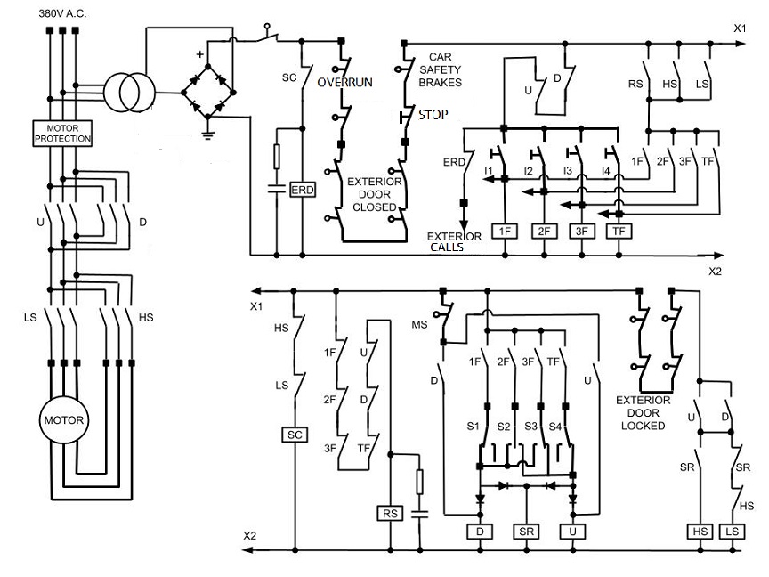
On old relay logic elevators, the car takes the right direction due to selectors
mounted in the shaft at each floor. These
selectors are turned by a shape mounted on the car. The image below shows a relay logic elevator
diagram, made just for educational
purpose. In the video below, you can see how the ralays work while the elevator moves
from the second to the top floor.
Once you supply the circuit, the relays (SC and RS) are energized if the doors
are closed. When you press the
request button, the top
floor relay gets energized. The speed coil and the direction contactor
are also supplied. The reset relay keeps
on until the capacitor discharges. The door locking coil (mounted on the car) is
energized by a contact of the direction contactor.
When the door is locked, the high speed contactor turns on and the elevator starts moving.
The level proximity switch gets closed, and the direction selector of the second floor takes the down position.
Once the elevator comes close to the top floor, the direction selector opens. The direction contactor is still
activated because it is self-powered, while the speed relay gets off because of the diode.
The low speed contactor turns on instead of the high speed
one. The request relay turns off. When the elevator reaches the top floor, the level
proximity switch opens, so the contactors
and the door locking coil get off. The reset relay is supposed to reset the circuit condition if, for some reason,
the elevator does not start moving (for example, a malfunction on the locked door switch). |

|